

ESM: Built-in ultra-conformal interface of perfluorinated electrolyte for practical high-energy lithium batteries
By hoppt
Research Background
In lithium-ion batteries, to achieve the goal of 350 Wh Kg-1, the cathode material uses nickel-rich layered oxide (LiNixMnyCozO2, x+y+z=1, called NMCxyz). With the increase of energy density, the dangers related to thermal runaway of LIBs have attracted people's attention. From a material perspective, nickel-rich positive electrodes have serious safety issues. In addition, oxidation/crosstalk of other battery components, such as organic liquids and negative electrodes, can also trigger thermal runaway, which is considered the leading cause of safety problems. The in-situ controllable formation of a stable electrode-electrolyte interface is the primary strategy for the next generation of high-energy-density lithium-based batteries. Specifically, a solid and dense cathode-electrolyte interphase (CEI) with higher thermal stability inorganic components can solve the safety problem by inhibiting the release of oxygen. So far, there is a lack of research on CEI cathode-modified materials and battery-level safety.
Achievement display
Recently, Feng Xuning, Wang Li, and Ouyang Minggao of Tsinghua University published a research paper entitled "In-Built Ultraconformal Interphases Enable High-Safety Practical Lithium Batteries" on Energy Storage Materials. The author evaluated the safety performance of the practical NMC811/Gr soft-packed full battery and the thermal stability of the corresponding CEI positive electrode. The thermal runaway suppression mechanism between the material and the soft pack battery has been comprehensively studied. Using a non-flammable perfluorinated electrolyte, an NMC811/Gr pouch-type full battery was prepared. The thermal stability of NMC811 was improved by the in-situ formed CEI protective layer rich in inorganic LiF. The CEI of LiF can effectively alleviate the oxygen release caused by the phase change and inhibit the exothermic reaction between the delighted NMC811 and the fluorinated electrolyte.
Graphic guide
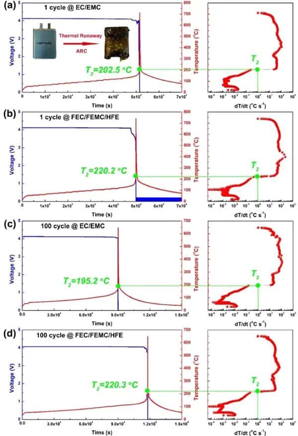
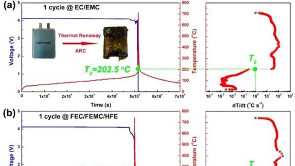
Figure 1 Comparison of thermal runaway characteristics of practical NMC811/Gr pouch-type full battery using perfluorinated electrolyte and conventional electrolyte. After one cycle of traditional (a) EC/EMC and (b) perfluorinated FEC/FEMC/HFE electrolyte pouch type full batteries. (c) Conventional EC/EMC electrolysis and (d) perfluorinated FEC/FEMC/HFE electrolyte pouch-type full battery aged after 100 cycles.
For the NMC811/Gr battery with traditional electrolyte after one cycle (Figure 1a), T2 is at 202.5°C. T2 occurs when the open-circuit voltage drops. However, the T2 of the battery using the perfluorinated electrolyte reaches 220.2°C (Figure 1b), which shows that the perfluorinated electrolyte can improve the inherent thermal safety of the battery to a certain extent due to its higher thermal stability. As the battery ages, the T2 value of the traditional electrolyte battery drops to 195.2 °C (Figure 1c). However, the aging process does not affect the T2 of the battery using perfluorinated electrolytes (Figure 1d). In addition, the maximum dT/dt value of the battery using the traditional electrolyte during TR is as high as 113°C s-1, while the battery using the perfluorinated electrolyte is only 32°C s-1. The difference in T2 of aging batteries can be attributed to the inherent thermal stability of delighted NMC811, which is reduced under conventional electrolytes, but can be effectively maintained under perfluorinated electrolytes.
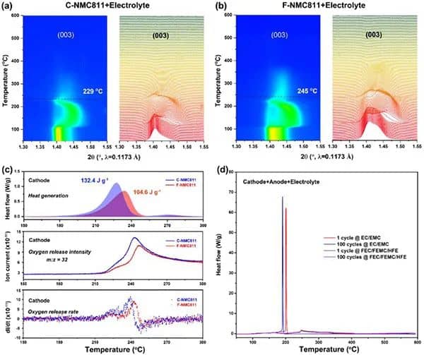
Figure 2 Thermal stability of delithiation NMC811 positive electrode and NMC811/Gr battery mixture. (A,b) Contour maps of C-NMC811 and F-NMC811 synchrotron high-energy XRD and the corresponding (003) diffraction peak changes. (c) The heating and oxygen release behavior of the positive electrode of C-NMC811 and F-NMC811. (d) DSC curve of sample mixture of the delighted positive electrode, lithiated negative electrode, and electrolyte.
Figures 2a and b show the HEXRD curves of delighted NMC81 with different CEI layers in the presence of conventional electrolytes and during the period from room temperature to 600°C. The results clearly show that in the presence of an electrolyte, a strong CEI layer is conducive to the thermal stability of the lithium-deposited cathode. As shown in Figure 2c, a single F-NMC811 showed a slower exothermic peak at 233.8°C, while the C-NMC811 exothermic peak appeared at 227.3°C. In addition, the intensity and rate of oxygen release caused by the phase transition of C-NMC811 are more severe than those of F-NMC811, further confirming that robust CEI improves the inherent thermal stability of F-NMC811. Figure 2d performs a DSC test on a mixture of delighted NMC811 and other corresponding battery components. For conventional electrolytes, the exothermic peaks of samples with 1 and 100 cycles indicate that the aging of the traditional interface will reduce thermal stability. In contrast, for the perfluorinated electrolyte, the illustrations after 1 and 100 cycles show broad and mild exothermic peaks, in line with the TR trigger temperature ( T2). The results (Figure 1) are consistent, indicating that the strong CEI can effectively improve the thermal stability of the aged and delighted NMC811 and other battery components.
Figure 3 Characterization of delighted NMC811 positive electrode in the perfluorinated electrolyte. (a-b) Cross-sectional SEM images of the aged F-NMC811 positive electrode and corresponding EDS mapping. (c-h) Element distribution. (i-j) Cross-sectional SEM image of the aged F-NMC811 positive electrode on virtual x-y. (k-m) Reconstruction of 3D FIB-SEM structure and spatial distribution of F elements.
To confirm the controllable formation of fluorinated CEI, the cross-sectional morphology and element distribution of the aged NMC811 positive electrode recovered in the actual soft-pack battery were characterized by FIB-SEM (Figure 3 a-h). In the perfluorinated electrolyte, a uniform fluorinated CEI layer is formed on the surface of F-NMC811. On the contrary, C-NMC811 in the conventional electrolyte lacks F and forms an uneven CEI layer. The F element content on the cross-section of F-NMC811 (Figure 3h) is higher than that of C-NMC811, which further proves that the in-situ formation of the inorganic fluorinated mesophase is the key to maintaining the stability of delighted NMC811. With the help of FIB-SEM and EDS mapping, as shown in Figure 3m, it observed many F elements in the 3D model on the surface of F-NMC811.
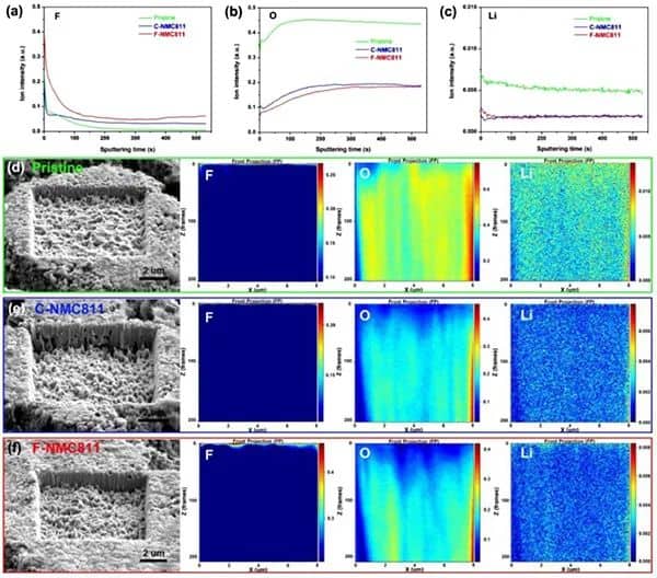
Figure 4a) Element depth distribution on the surface of the original and delighted NMC811 positive electrode. (a-c) FIB-TOF-SIMS is sputtering the distribution of F, O, and Li elements in the positive electrode of NMC811. (d-f) The surface morphology and depth distribution of F, O, and Li elements of NMC811.
FIB-TOF-SEM further revealed the depth distribution of elements on the surface of the positive electrode of NMC811 (Figure 4). Compared with the original and C-NMC811 samples, a significant increase in F signal was found in the top surface layer of F-NMC811 (Figure 4a). In addition, the weak O and high Li signals on the surface indicate the formation of F- and Li-rich CEI layers (Figure 4b, c). These results all confirmed that F-NMC811 has a LiF-rich CEI layer. Compared with the CEI of C-NMC811, the CEI layer of F-NMC811 contains more F and Li elements. In addition, as shown in FIGS. 4d-f, from the perspective of ion etching depth, the structure of the original NMC811 is more robust than that of the delighted NMC811. The etch depth of aged F-NMC811 is smaller than C-NMC811, which means that F-NMC811 has excellent structural stability.
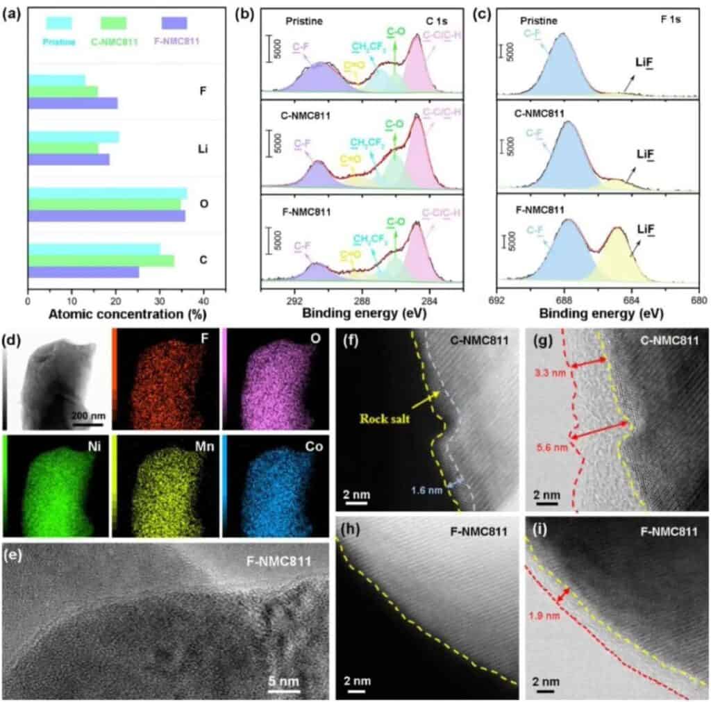
Figure 5 CEI chemical composition on the surface of the positive electrode of NMC811. (a) XPS spectrum of NMC811 positive electrode CEI. (b-c) XPS C1s and F1s spectra of the original and delighted NMC811 positive electrode CEI. (d) Cryo-transmission electron microscope: element distribution of F-NMC811. (e) Frozen TEM image of CEI formed on F-NMC81. (f-g) STEM-HAADF and STEM-ABF images of C-NMC811. (h-i) STEM-HAADF and STEM-ABF images of F-NMC811.
They used XPS to characterize the chemical composition of CEI in NMC811 (Figure 5). Unlike the original C-NMC811, the CEI of F-NMC811 contains a large F and Li but minor C (Figure 5a). The reduction of C species indicates that LiF-rich CEI can protect F-NMC811 by reducing the sustained side reactions with electrolytes (Figure 5b). In addition, smaller amounts of C-O and C=O indicate that the solvolysis of F-NMC811 is limited. In the F1s spectrum of XPS (Figure 5c), F-NMC811 showed a powerful LiF signal, confirming that CEI contains a large amount of LiF derived from fluorinated solvents. The mapping of the F, O, Ni, Co, and Mn elements in the local area on the F-NMC811 particles shows that the details are uniformly distributed as a whole (Figure 5d). The low-temperature TEM image in Figure 5e shows that CEI can act as a protective layer to uniformly cover the NMC811 positive electrode. To further confirm the structural evolution of the interface, high-angle circular dark-field scanning transmission electron microscopy (HAADF-STEM and circular bright-field scanning transmission electron microscopy (ABF-STEM) experiments were carried out. For the carbonate electrolyte (C-NMC811), The surface of the circulating positive electrode has undergone a severe phase change, and a disordered rock salt phase is accumulated on the surface of the positive electrode (Figure 5f). For the perfluorinated electrolyte, the surface of the F-NMC811 positive electrode maintains a layered structure (Figure 5h), indicating harmful The phase becomes effectively suppressed. In addition, a uniform CEI layer was observed on the surface of F-NMC811 (Figure 5i-g). These results further prove the uniformity of the CEI layer on the positive electrode surface of NMC811 in the perfluorinated electrolyte.
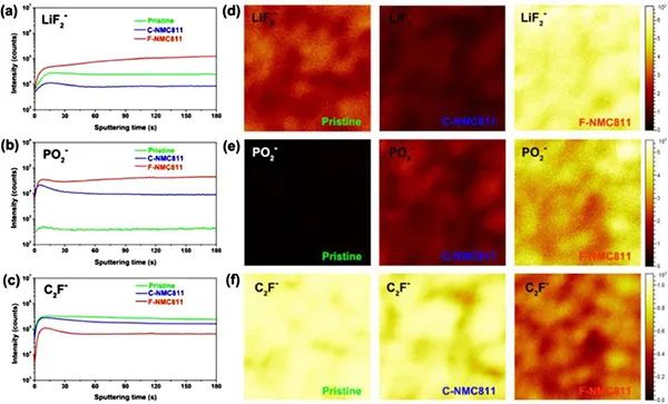
Figure 6a) TOF-SIMS spectrum of the interphase phase on the surface of the NMC811 positive electrode. (a-c) In-depth analysis of specific second ion fragments on the positive electrode of NMC811. (d-f) TOF-SIMS chemical spectrum of the second ion fragment after 180 seconds of sputtering on the original, C-NMC811 and F-NMC811.
C2F-fragments are generally considered organic substances of CEI, and LiF2- and PO2-fragments are usually regarded as inorganic species. Significantly enhanced signals of LiF2- and PO2- were obtained in the experiment (Figure 6a, b), indicating that the CEI layer of F-NMC811 contains a large number of inorganic species. On the contrary, the C2F-signal of F-NMC811 is weaker than that of C-NMC811 (Figure 6c), which means that the CEI layer of F-NMC811 contains less fragile organic species. Further research found (Figure 6d-f) that there are more inorganic species in the CEI of F-NMC811, while there are fewer inorganic species in C-NMC811. All these results show the formation of a solid inorganic-rich CEI layer in the perfluorinated electrolyte. Compared with the NMC811/Gr soft-pack battery using a traditional electrolyte, the safety improvement of the soft-pack battery using perfluorinated electrolyte can be attributed to: First, the in-situ formation of a CEI layer rich in inorganic LiF is beneficial. The inherent thermal stability of the delighted NMC811 positive electrode reduces the release of lattice oxygen caused by phase transition; secondly, the solid inorganic CEI protective layer further prevents the highly reactive delithiation NMC811 from contacting the electrolyte, reducing the exothermic side reaction; third, The perfluorinated electrolyte has high thermal stability at high temperatures.
Conclusion and Outlook
This work reported the development of a practical Gr/NMC811 pouch-type full battery using a perfluorinated electrolyte, which significantly improved its safety performance. Intrinsic thermal stability. An in-depth study of the TR inhibition mechanism and the correlation between materials and battery levels. The aging process does not affect the TR trigger temperature (T2) of the perfluorinated electrolyte battery during the entire storm, which has obvious advantages over the aging battery using the traditional electrolyte. In addition, the exothermic peak is consistent with the TR results, indicating that the strong CEI is conducive to the thermal stability of the lithium-free positive electrode and other battery components. These results show that the in-situ control design of the stable CEI layer has important guiding significance for the practical application of safer high-energy lithium batteries.
Literature information
In-Built Ultraconformal Interphases Enable High-Safety Practical Lithium Batteries, Energy Storage Materials, 2021.

